20 Results
View results:
Sort by:

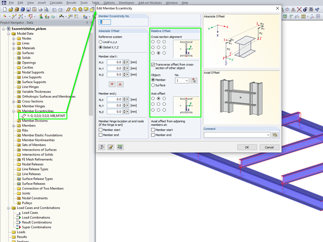
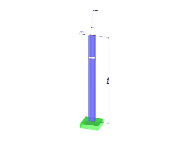
For the stability verification of members using the equivalent member method, it is necessary to define effective or lateral-torsional buckling lengths in order to determine a critical load for stability failure. In this article an RFEM 6-specific function is presented, by which you can assign an eccentricity to the nodal supports and thus influence the determination of the critical bending moment considered in the stability analysis.

For cross‑laminated structures with large spans, downstand beams or hybrid structures are often used. They can be modeled in RFEM 5 by using surfaces and member cross‑sections. In both structural systems, curved downstand beams are also possible without any problems. In the case of the curved surface, the member is always appropriately generated by means of the automatic member eccentricity with the thickness distance of the surface and the member. The downstand beam can also be connected flexibly by means of a line release.
In RFEM 5 and RSTAB 8, you can enter eccentricities for surfaces and members using the convenient "Select" function.
RF‑/FOUNDATION Pro allows you to check the allowable eccentricity of the soil pressure resultants. According to DIN EN p;1997‑1/NA, this design is to be carried out with characteristic or representative loads.
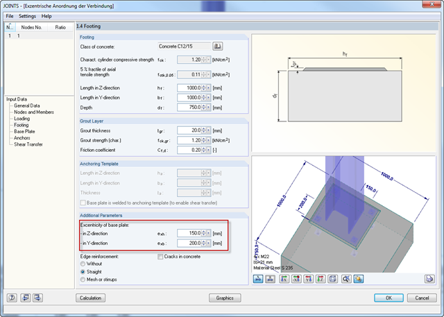
For structural reasons, it may be necessary for a base plate not to be set centrically on a foundation. Therefore, an eccentric arrangement of the base plate is possible in RF‑/JOINTS Steel - Column Base by entering the parameters for the respective direction in Window 1.4.

If a rib is part of a nonlinear design or is rigidly connected to following walls, a surface should be used for the modeling instead of a member. So that the rib can still be designed as a member, a result member with the correct eccentricity is required, which transforms the surface internal forces into member internal forces.
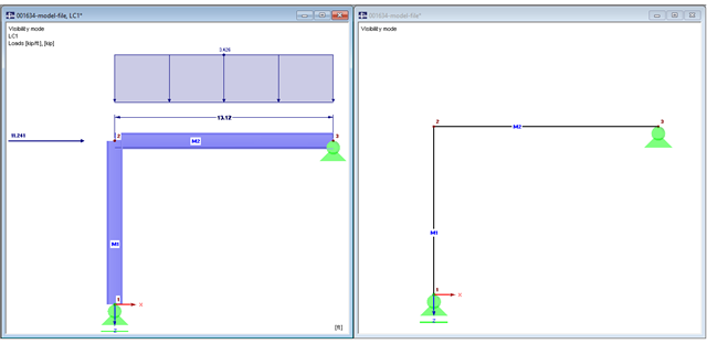
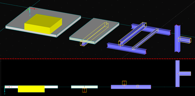
The beam is resting on the column, and the beam ends at the outer edge of the column. These requirements can be fulfilled easily in an architectural model with solids. In member analysis, simplified line models are used in which center lines meet in a common node. In this article, the influence of member eccentricities on the determination of internal forces is shown on three simple models.

In order to consider inaccuracies regarding the position of masses in a response spectrum analysis, standards for seismic design specify rules that have to be applied in both the simplified and multi-modal response spectrum analyses. These rules describe the following general procedure: The story mass must be shifted by a certain eccentricity, which results in a torsional moment.
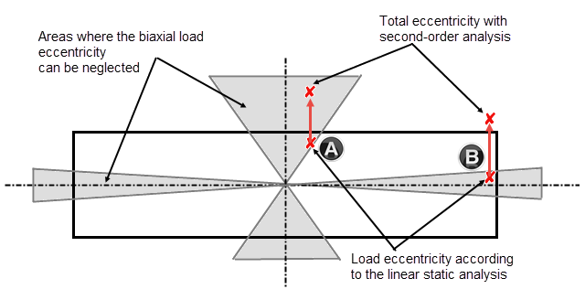
Daily tasks in reinforced concrete design also include designing compression elements subjected to biaxial bending. The following article describes the different methods according to Chapter 5.8.9, EN 1992-1-1, which can be used to design compression elements with biaxial load eccentricities by means of the nominal curvature method according to 5.8.8.
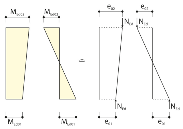
When calculating the internal forces for the buckling analysis with the method based on nominal curvature in RF‑CONCRETE Columns, the required eccentricities have to be determined.
Using RF-/FOUNDATION Pro, it is possible to perform geotechnical design according to EN 1997-1 [1] for single foundations. The following article explains the design of highly eccentric loading in the foundation core according to DIN EN 1997‑1, A 6.6.5 (see [3]).
In the case of a parallel offset of the structural plane of members and surfaces and also applying an axial offset to members, for example, the function of eccentricities may be useful.
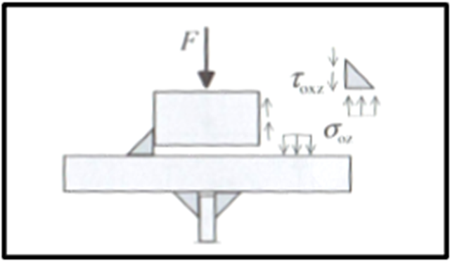
Based on the technical article about the ultimate limit state design of rail welds, the following explanation refers to the process of fatigue design of rail welds. In particular, this article explains in detail the effects of considering an eccentric wheel load of 1/4 of the rail head width.
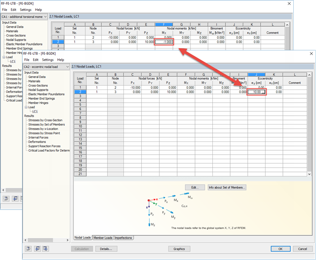
There are two ways to specify eccentric nodal loads in RF-/FE-LTB. First, the nodal load has to be applied in the right direction. Then, you can assign either the resulting torsional moment or the eccentricity.
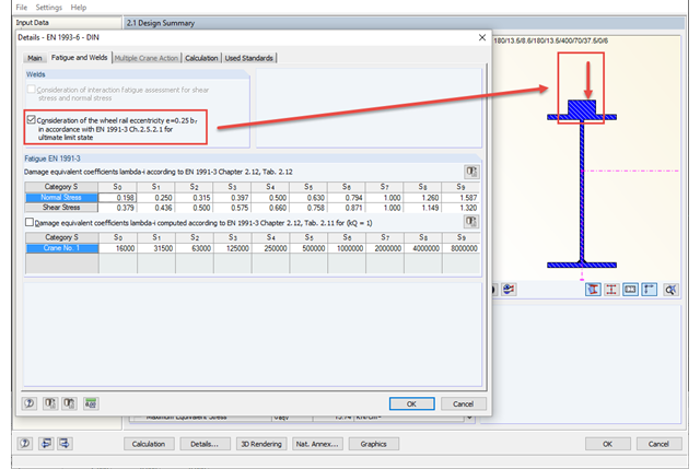
The eccentric wheel load application of 1/4 of the rail head width has to be considered only for fatigue design from damage class S3 according to DIN EN 1993‑6. An additional input option in detail settings allows you to consider this eccentricity for fatigue design at the ultimate limit state as well. By selecting this option, the design with the eccentric load applied is always considered without regard to the damage class.

In the case of tension connections with cleats subjected to unilateral loading, the external members (side timber) are loaded by an additional bending moment due to the eccentric load distribution. However, this fact is not mentioned in EN 1995‑1‑1 and is considered in the National Annex to DIN EN 1995‑1‑1 by the reduction of the tensile strength. This reduction depends on the pull-off strength of the fasteners.
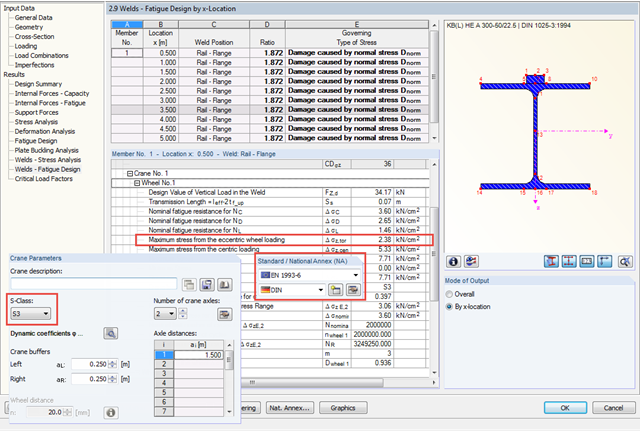
In CRANEWAY, the eccentric wheel loading of 1/4 of the rail head width is used for the fatigue design of welds as well as for craneway girder design according to the National Annex of Germany and as of damage class S3.
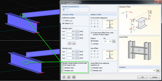
When modeling eccentric members with member hinges, RFEM provides the option to assign the hinge to the start or end of the member eccentricity. There is another option for creating and displaying the structural system more precisely in the design.
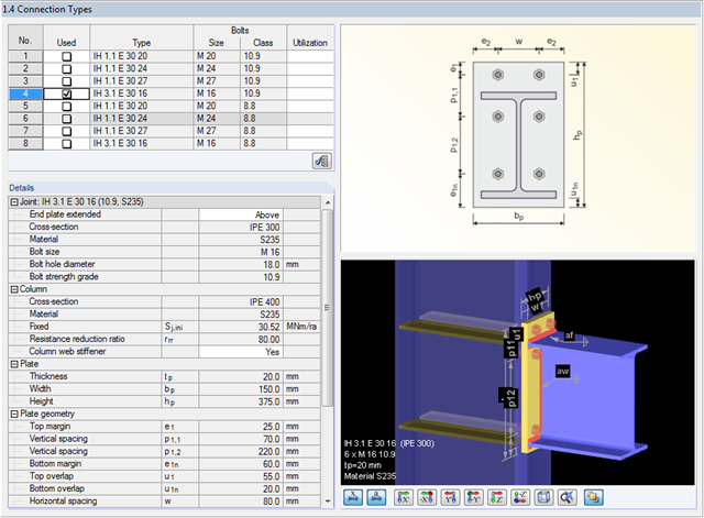
Starting with version X.05.0018, you can also analyze moment-resistant beam-column connections in RF‑/JOINTS Steel - DSTV. Both single-sided and double-sided connections are possible. In compliance with the DSTV guidelines, the program checks (with respect to the loading) whether the existing column cross‑section is dimensioned sufficiently. Optionally, you can transfer the rotational stiffness and the eccentricity of the connection to RFEM or RSTAB.
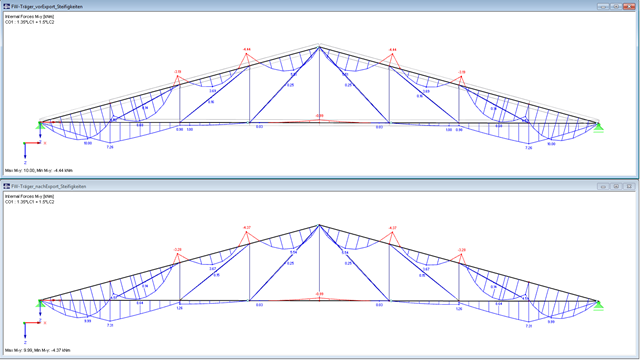
In RF-/JOINTS Timber - Steel to Timber, you can consider the eccentricities of a connection during the calculation. The figure shows different internal forces without consideration of the eccentricity (above) and withn consideration of the eccentricity (below).